LS-TaSC
What is Topology Optimization?
Topology optimization is a structural design optimization technique for distributing material efficiently across the design domain by changing the topology of the design for a given set of loading and boundary conditions such that, the resulting design has better performance targets in terms of improved stiffness, and reduced mass.
In topology optimization, the overall topology of the structure is varied by removing unwanted material from the structure such that the final design is lighter without compromising the performance characteristics.
LS-TaSC
LS-TaSC is a topology and shape computation tool of LS-DYNA suite developed by Livermore Software Technology Corporation.
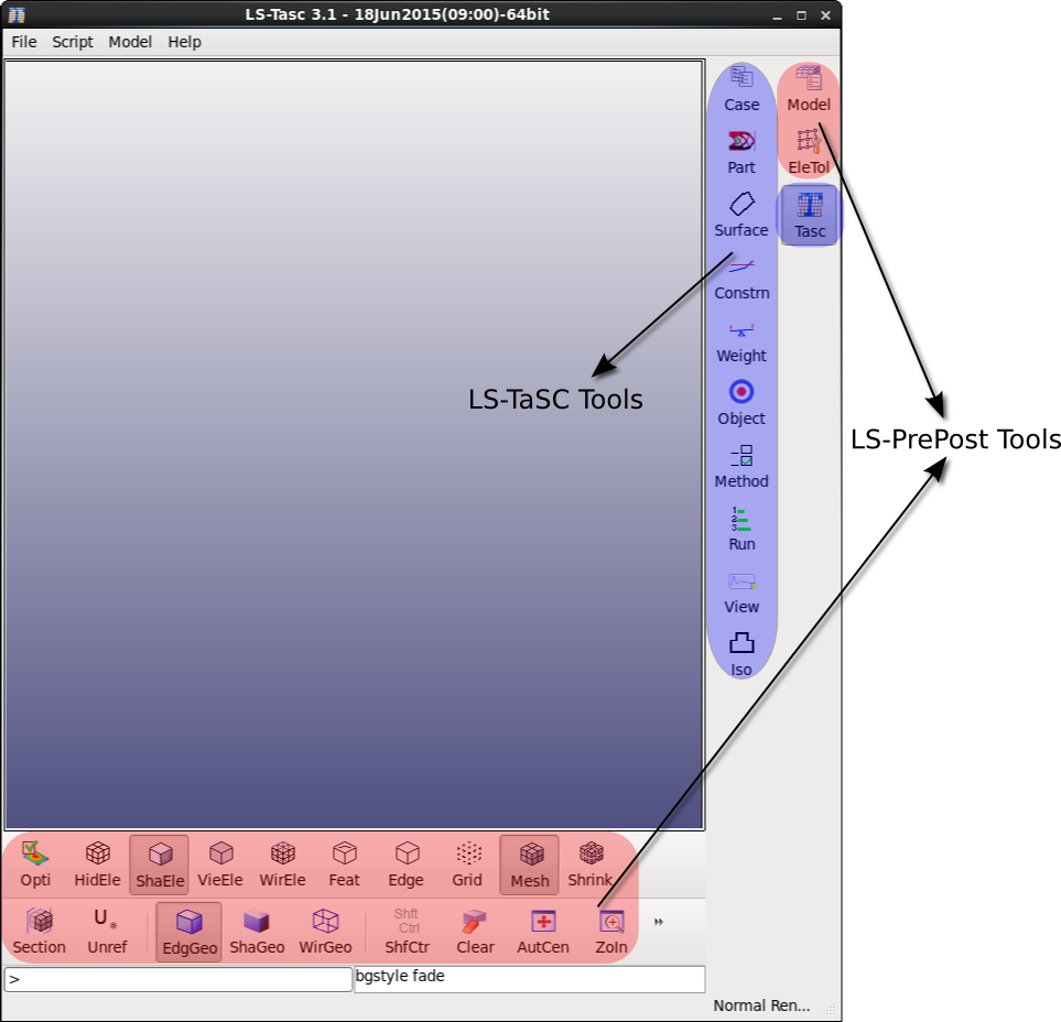
Figure 1: User Interface of LS-TaSC 3.1
In LS-TaSC, the goal is to obtain a structure with uniform energy density distribution to suit crashworthiness applications where internal energy absorption of the design parts is important.
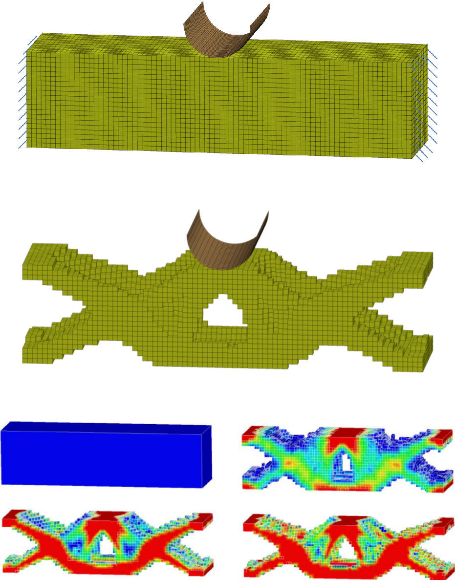
Figure 2: Starting design of the beam, optimized form of the beam and the topology evolution with element density contours.
Case
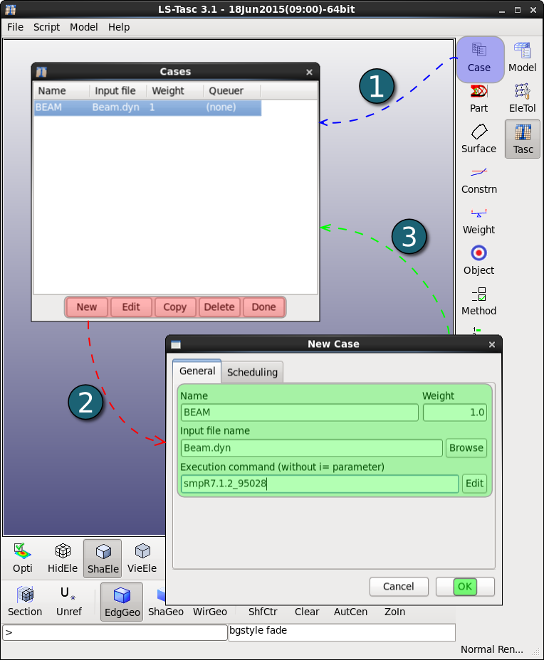
A case in LS-TaSC corresponds to the loading and boundary conditions of the structure and the resulting topology from optimization will be in accordance to this load case.
A structure designed for a single load case can perform badly in with respect to other load cases. Therefore, the multiple load case feature of LS-TaSC allows designing of structures in terms of multiple loading conditions.
Any number of load cases can be added but a unique name should be provided for each case with input being the LS-DYNA keyword file. LS-DYNA executable should be selected as the solver command. Any LS-DYNA command line options such as memory, no. of CPUs, ... can be entered directly in the command section.
Any job scheduling options such as selection of a queuing system has to be defined in the case panel Scheduling tab.
Part
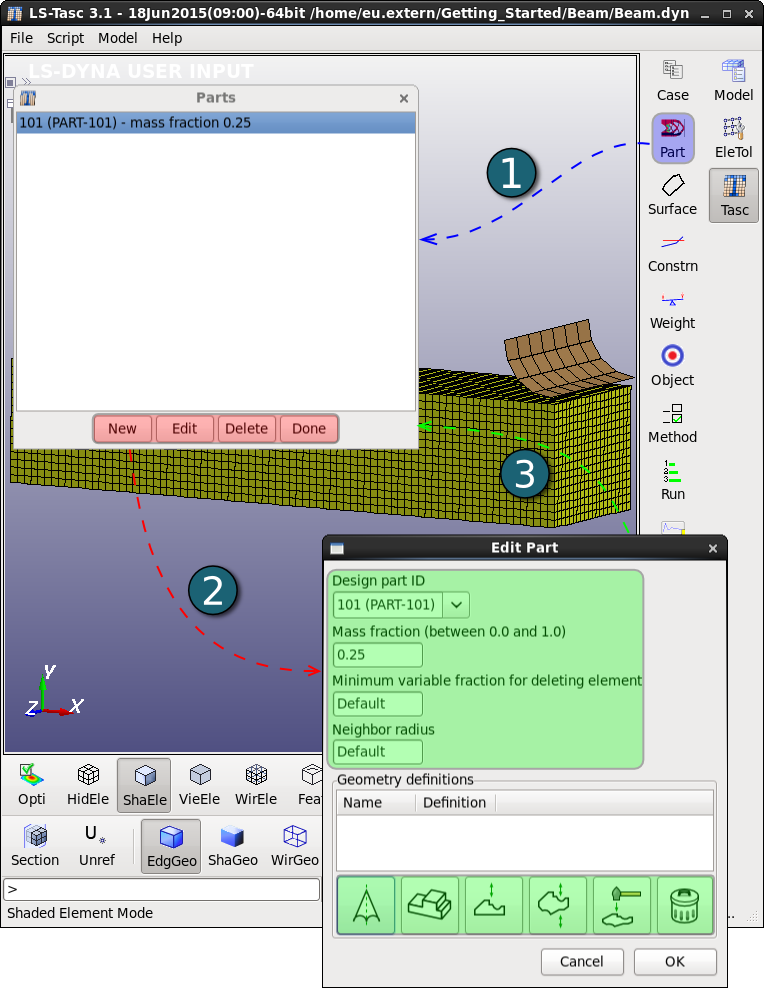
The Part dialogue box has options to select the part to be optimized and define few optimization parameters such as mass fraction, minimum variable fraction for element deletion, element neighbor radius and geometry definitions.
LS-TaSC does not have a limit in terms of number of parts to be optimized. Hence multiple parts can be defined and each part should be assigned optimization parameters separately.
Mass fraction is the amount of mass to be retained after optimization process. A mass fraction of 0.25 indicates for example that LS-TaSC will try to retain 25% mass of the part.
A minimum variable fraction can be specified by the user, elements with design variable values below this limit will be deleted, which is 0.05 for non-linear problems and 0.001 for linear problems by default.
The design variables of all the elements are updated based on field variable (internal energy density) values of the neighboring elements. A virtual sphere with a radius is defined and elements within this radius are considered to be the neighboring elements (refer to LS-TaSC User’s manual for more information). The default Neighbor Radius value is -1.0, which means the results from all elements sharing a node with an element are likely to be used.
Geometry and manufacturing definitions such as symmetry, casting, extrusion and forging can be defined for the part being optimized. Within casting, both one way and two way casting can be defined. There are limitations in terms of number of geometry definitions. A maximum of three geometry definitions can be assigned to each part with maximum of two casting definitions.
Method
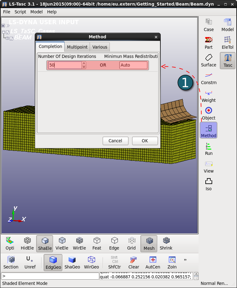
The termination criteria for the optimization process in terms of maximum number of iterations and optimization convergence tolerance are defined in this panel.
For topology design the minimum mass redistribution is used to stop the search when the topology has evolved sufficiently. This convergence tolerance is compared to the Mass_Redistribution history variable displayed in the view panel. The default value is 0.002.
For surface design the convergence tolerance indicates how much the surface stress was smoothed: a value of 1 indicates that a uniform surface stress was achieved, while a value of 0 indicates no improvement. The value is relative to the initial variation of the surface stress – so a value of 0.5 will indicate a 50% reduction of the initial surface stress variation.
Run
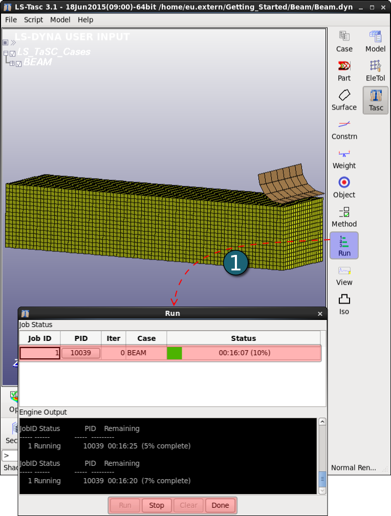
This panel is used to start, stop or to restart the optimization process.
The job progress and LS-TaSC engine output information is also displayed in this panel.
View
The view panel is similar to a postprocessor. Various topology histories plots such as change in mass fraction, element fraction, constraint values etc over the iterations are displayed in this panel. The model plots options are used to view d3plot data of iterations.
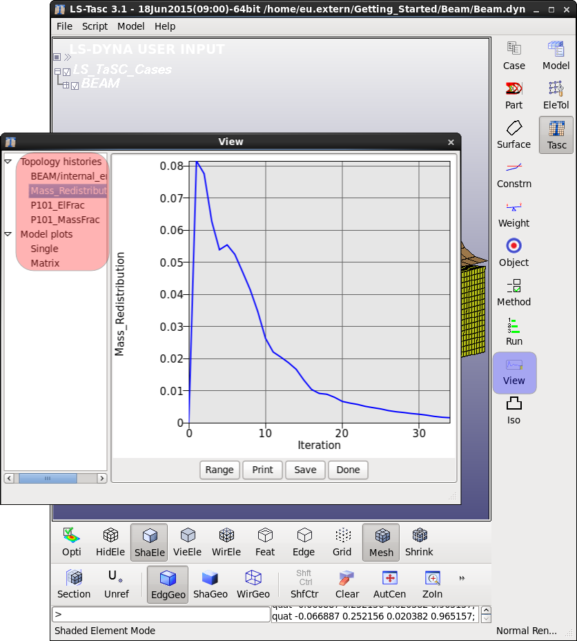
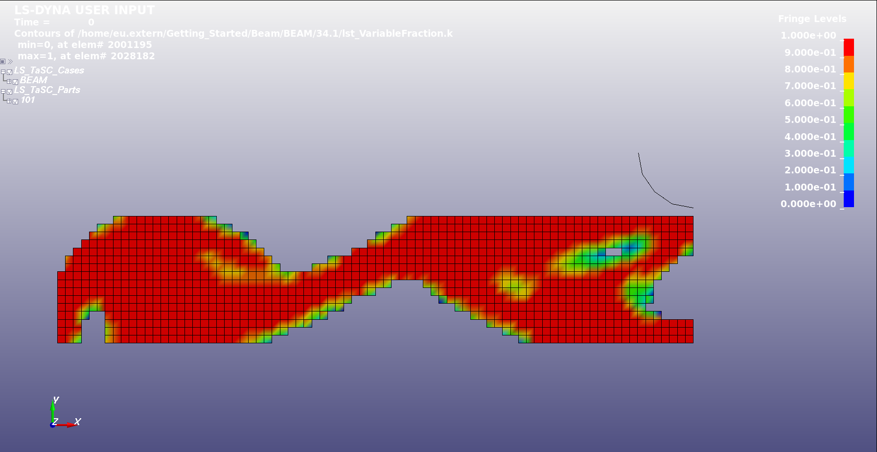
Figure 01: Final topology
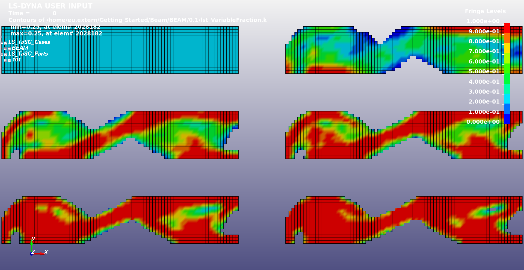
Figure 02: The topologies at different iterations
