Stage
https://www.lsoptsupport.com/examples/subpages/crash_linear/copy3_of_results-tabbed
https://www.lsoptsupport.com/@@site-logo/LS-Opt-Support-Logo480x80.png
Stage
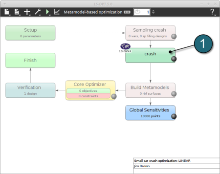
Home Screen Process Flowchart
- Double click on the crash box.
A window Stage crash shall open.
Define Input File Name and Command
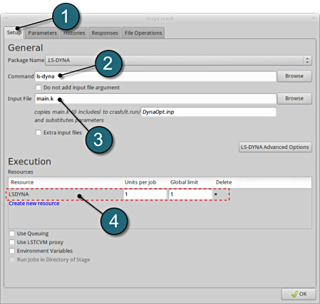
- Select the Setup tab.
- For Command specify the LS-DYNA executable ls-dyna (This name can be different on your computer). On Windows, the command has to be specified using the absolute path.
- For Input File browse the parameterized file main.k. Parameters in LS-DYNA input files can be defined using *PARAMETER or the LS-OPT parameter format <<>>.
- For efficient usage of the computing power from the machine, choice on handling number of concurrent jobs can be made suitably in this section. (E.g., if the machine has 4CPUs, and to run each job on a single CPU : Units per job = 1, Global limit = 4).
The parameters located in the selected Input File can be visualized in the adjoining tab Parameters.
Design Parameters.
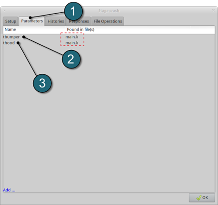
- Select the Parameters tab.
- The first design parameter located in the input file main.k is displayed (In this case the thickness of the bumper, denoted as tbumper ).
- The second design parameter located in the input file main.k is displayed (In this case the thickness of the hood, denoted as thood ).
- The input file main.k is shown below for reference.
*KEYWORD
*PARAMETER
rtbumper,3.0,rthood,1.0
*INCLUDE
../../car5.k
*END
Responses for Optimization
- The various responses for the optimization problem can be related to the car crash diagram shown below.
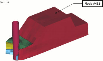
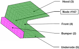
Fig. 1(a): Deformed vehicle after 50 msFig. 1(b): Design variables with part numbers
Add First Response
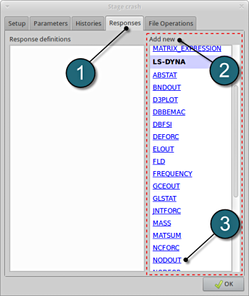
- Click on the Responses tab.
- Select the suitable response type from the various option available from the list under Add new.
- For the first response select the option NODOUT , which represents an interface to LS-DYNA nodout results. Note that LS-OPT reads the results from the binout database.
A separate window emerges named; Edit response. This enables the user to define the response in suitable steps.
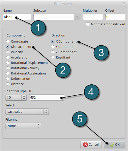
Define x-displacement of node 432
- For Response name enter Disp2.
- For Component select from the list Displacement.
- For Direction select X Component.
- For node ID enter 432.
- Click on the OK button to add the response.
- The Edit response tab closes and returns to the main page of the Responses tab in the Stage crash window.
Add Second Response
- To add an additional response select from the option NODOUT from the Add new on the Responses tab.
Define x-displacement of node 167
- To add the second response repeat in the similar manner for Response name Disp1 with node ID 167.
Add Third Response
- To add an additional response select from the option NODOUT from the Add new on the Responses tab.
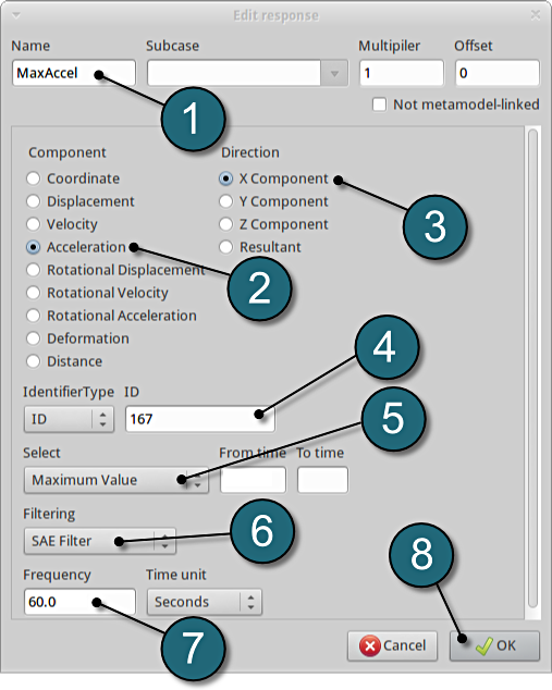
Define x-acceleration of node 167
- For Response name enter MaxAccel.
- For Component select from the list Acceleration.
- For Direction select X Component.
- For node ID enter 167.
- Select the Maximum Value option under Select. This will choose the max. value of acceleration in x-direction during the crash.
- For Filtering choose SAE Filter.
- Enter 60.0 for Frequency.
- Click on the OK button to add the response.
- The Edit response tab closes and returns to the main page of the Responses tab in the Stage crash window.
Add Fourth Response
- To add an additional response select from the option Injury from the Add new on the Responses tab.
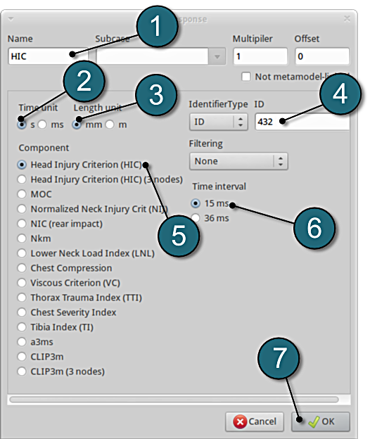
Define head injury coefficient of node 432
- For Response name enter HIC.
- For Time unit select s.
- For Length unit select mm.
- For Node ID enter 432.
- For Component select from the list Head Injury Criterion (HIC).
- For Time interval select 15 ms.
- Click on the OK button to add the response.
- The Edit response tab closes and returns to the main page of the Responses tab in the Stage crash window.
Add Fifth Response
- To add an additional response select from the option Mass from the Add new on the Responses tab.
Define mass responses for structural components
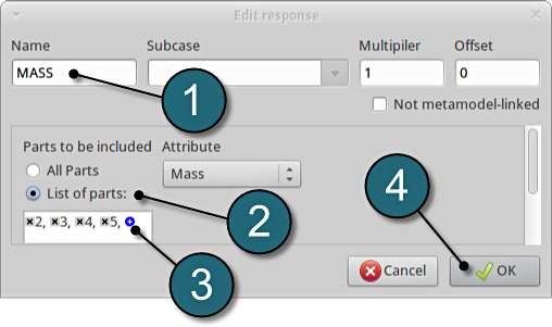
- For Response name enter Mass.
- For Parts to be included select List of parts.
- In the empty box underneath enter 2. Push the add button (denoted as +) to add the various parts 3, 4 and 5.
- The part ID numbers can be found in Fig. 1 ( shown above ) bumper (2), hood (3), front (4) and underside (5).
- Click on the OK button to add the response.
- The Edit response tab closes and returns to the main page of the Responses tab in the Stage crash window.
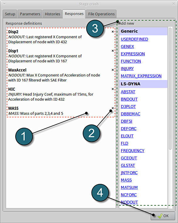
Responses Review
- The defined responses can be reviewed in the tab of the Responses under the Response definition. Necessary changes can be made by selecting the choice.
- To delete a Response definition click on the cross button (denoted as X).
- Additional responses can be added from the choice available under the Add new list as earlier.
- Click on the OK button to proceed.
