Load case US_NCAP
Define x-acceleration of nodes: - Select the Histories tab.
- From the possible history types select: NODOUT.
- For Component select from the list Acceleration.
- For Direction select X Component.
- For Node ID enter 3740178.
(The acceleration of the left seat is measured by node 3740178.
To see the position of the node click on the ID-number.) - For Filtering choose SAE Filter.
- Enter 60.0 for Frequency.
- For Case switch to US_NCAP.
- For History Name enter accel_left_seat.
- Push the Add button.
For the rest of the Acceleration-Histories ( e.g. accel_right_seat, accel_engine_top, accel_engine_bottom, accel_B_pillar_r, accel_B_pillar_l ) repeat the steps 2 to 10, updating only the Node IDs and Names. | 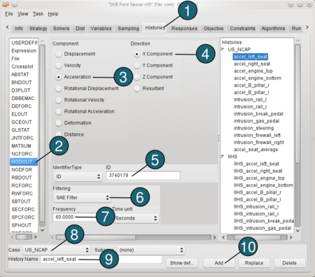
|
Define intrusion: - From the possible history types select: NODOUT.
- For Component select from the list Deformation.
- For Direction select X Component.
- For Coordinate System select Local.
- For Identifier Type switch to ID.
- For Local x-axis from enter 2362340 to 2352390, 3rd node ID 2214602.
- For Measured Node ID enter 2057404.
(To see the position of the node click on the ID-number.) - For Reference Node ID enter 2362340.
- For Filtering choose None.
- For Case switch to US_NCAP.
- For History Name enter intrusion_rail_l.
- Push the Add button.
For the rest of the Intrusion-Histories ( e.g. intrusion_rail_r, intrusion_break_pedal, intrusion_gas_pedal, intrusion_steering, intrusion_firewall_left, intrusion_firewall_right) repeat the steps 1 to 12, updating only the Measured Node IDs and Names. | 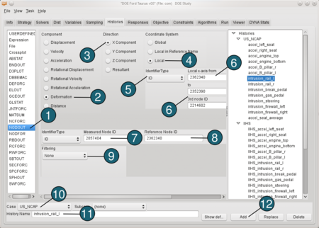 |
Define an Expression: Now we would like to calculate the average accelaration of a seat. Therefore we use the predefined histories accel_left_seat and accel_right_seat. - From the possible history types select: Expression.
- In the input field for an algebraic expression enter (accel_left_seat+accel_right_seat)/2.
- For Case switch to US_NCAP.
- For History Name enter accel_seat_average.
- Push the Add button.
Define the same histories for the load case IIHS, that you defined for the load case US_NCAP. | 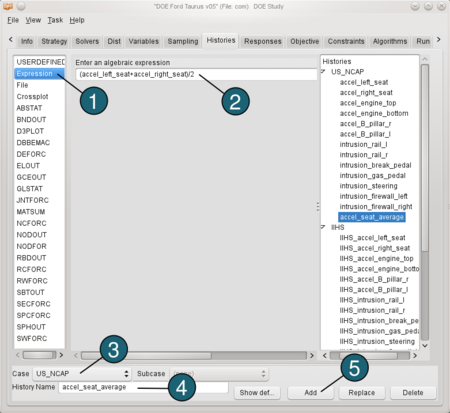 |
Load case Torsion
Define Displacement: - From the possible history types select: RBDOUT.
- For Rigid Body ID enter 2000804.
- For Component select from the list Displacement.
- For Direction select Z Component.
- For Case switch to Torsion.
- For History Name enter z_displ_2000804.
- Push the Add button.
Repeat steps 1 to 7 to define other displacements ( e.g. z_displ_2000805, y_displ_2000804, y_displ_2000805), updating the IDs, Directions and Names. | 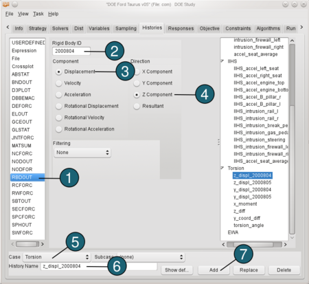 |
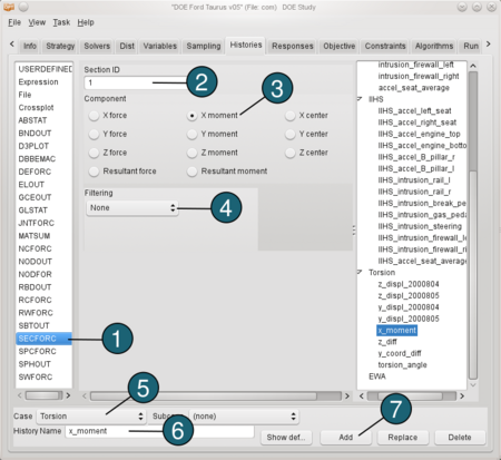
Define X-Moment: - From the possible history types select: SECFORC.
- For Section ID enter 1.
- For Component select from the list X moment.
- For Filtering choose None.
- For Case switch to Torsion.
- For History Name enter x_monent.
- Push the Add button.
|  |
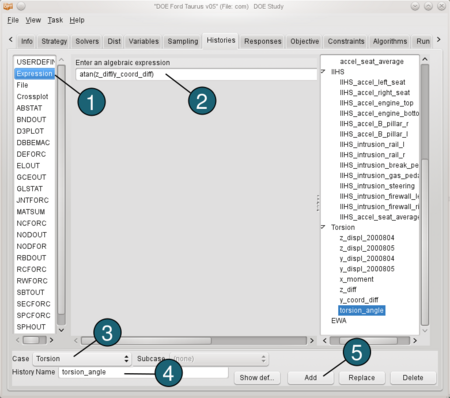
Define the torsion angle: We need to define two expressions before calculating torsion angle. The first one is the difference between the displacements in z direction we defined above (z_diff = z_displ_2000804 - z_displ_2000805). And the second one ist the difference between the coordinates of the displacements in y direction ( y_coord_diff = y_displ_2000804 - y_displ_2000805+1122.4566) The value 1122.4566 is the initial distance between the y coordinates. Now we can define the torsion angle: - From the possible history types select: Expression.
- In the input field for an algebraic expression enter atan(z_diff/y_coord_diff).
- For Case switch to Torsion.
- For History Name enter torsion_angle.
- Push the Add button.
|  |
